INTRODUCTION
With wide frequency band supporting range from 100 to 6000 MHz, the TESCOM Shield Box can be applied to most of the current and future wireless communication technologies such as GSM, WCDMA, WiMAX, LTE, GNSS, Bluetooth, and Wi-Fi. Therefore, the Shield Box can be used for mobile device measurement using multi-frequency bands without limitations and is ideal for mobile device measurement by maintaining stable and effective shielding performance in all frequency bands.
- Supports wide frequency band of 100 ~ 6000 MHz
- Applicable to all types of mobile phone measurement such as 2G, 3G, and 4G
- Applicable to wireless communication device measurement such as GPS/GLONSAS, Bluetooth, Wi-Fi, WiMAX, and LTE
- Provides various I/O interfaces
- Excellent shielding performance
- Solid structure and exceptional durability
- RS-232C control for automation
The most important feature of the Shield Box is the shielding of external interference signals that can be delivered to DUT. Depending on the measurement locations and testing environment, various signal interferences occur such as surrounding DUT signal, base station signal, and another measuring device´s signal, distorting the testing signal and lowering the reliability of measurement. However, the TESCOM Shield Box has secured stable shielding performance by using shield gasket and EMI filter in areas vulnerable to external interference signals such as I/O connectors, joints, and around doors.
In case of radiation testing environment using RF coupler for DUT connection inside a shield box, some problems may occur such as internal reflection, standing waves caused by scattered EM waves, and changes in transmitter characteristics and DUT antenna impedance. By using a powerful electromagnetic wave absorber to reduce the reflection and scattering of EM waves, the TESCOM Shield Box offers a stable EM wave environment despite its small footprint.
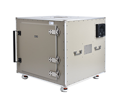
Because a shield box must perform repetitive opening and closing operations for several to thousands of times daily, its high durability is required. By using materials resistant to shock and corrosion, high-performance cylinder, and its related parts, the TESCOM Shield Box boasts of nearly zero likelihood of deformation; it is designed to maintain its performance despite more than a million operations.
When a shield box is used, DUT is connected by directly using cable or an antenna coupler. If interface for cable connection to DUT is available, the direct connection method is used; otherwise, a radiation measurement method with an antenna coupler is used. Since the results of radiation measurement change depending on the location of DUT, its fixture should maintain constant measurement conditions for repetitive measurements. TESCOM offers flexible fixtures that can change the location of the DUT fixture block. Depending on the shape of DUT, users can create its own fixture using two fixture blocks within seconds. Moreover, customized fixtures that meet the demands of customers can be manufactured and supplied if necessary. The various types of antenna coupler options with fixtures allow optimal measurement environment configuration that fits the characteristics of each DUT.
To meet various customer demands, TESCOM Shield Box interface panels are offered in the form of module. Customers can combine and order the necessary I/O interfaces for measurement. EMI filter is applied to all data interfaces to prevent signal leak.
| I/O Interface | Order Number | Data Speed / Line Voltage | * Shielding Effects |
|---|---|---|---|
 DB25, 1000pF pi Filter |
3409-0009-1 |
|
|
 DB25, 100pF pi Filter |
3409-0014-1 |
|
|
 DB9, 1000pF pi Filter |
3409-0008-1 |
|
|
 DB9, 100pF pi Filter |
3409-0010-1 |
|
|
 USB 2.0 Filter |
3409-0018A-3 |
|
|
 USB 3.0 Filter(Active) |
3409-0042A-1 |
|
|
 RJ-45 Filter |
3409-0022A |
|
|
 DC Power Adaptor |
3406-0004A |
|
|
 DC Power Adaptor, |
3406-0005A 3406-0006A |
|
|
 AC Power Adaptor |
3103-0009A |
|
|
| I/O Interface | Order Number | Frequency Range / Impedance / V.S.W.R |
|---|---|---|
 RF, N-SMA Connector |
3408-0038 | From DC to 6 GHz / 50 Ω / 1.15 max |
 RF, SMA-SMA Connector |
3408-0039 | From DC to 8 GHz / 50 Ω / 1.15 max |
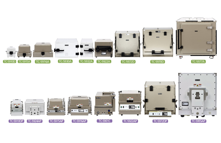
Selecting a Shield Box can largely depend on the size of DUT, connection methods, and measurement purpose. In general, customers need to consider the following prior to selecting a Shield Box:
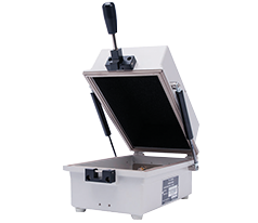
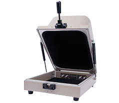
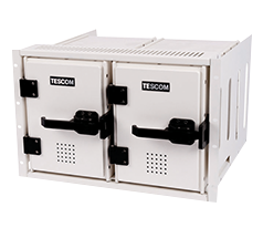
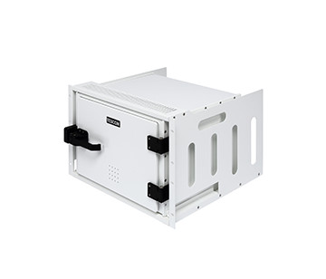
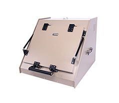
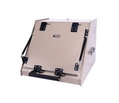
Depending on the operation methods, there are two types of Shield Box: manual and pneumatic. For development and quality control, repetitive opening and closing operations are not necessary; therefore, the manual type is appropriate. For places requiring repetitive operations, remote control using PC programs, and automation such as production lines, however, a pneumatic type of Shield Box is the better choice.
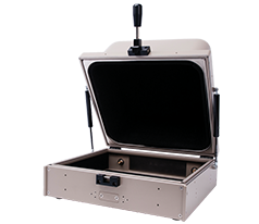
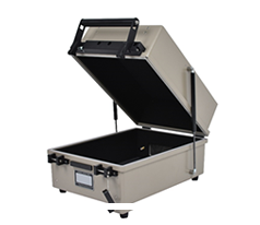
Select a Shield Box depending on the DUT size. If an antenna coupler is used, the energy density runs counter to the size of the Shield Box; therefore, when DUT is inserted, the effects of internal reflection waves can be minimized by securing sufficient space. In addition, when using a fixture or connecting cable inside, measurement errors can be reduced by allowing sufficient working space.
After selecting a Shield Box, choose the I/O interface panels for DUT; a fixture and an antenna coupler can then be selected for internal environment configuration depending on the measurement purpose.
